Step Groove Machining for Complex Steel Plate Edges is a practical production topic for teams that need to plan stepped and compound groove geometry. step groove machining should be treated as a controlled manufacturing decision rather than a setting copied from another job. The correct method depends on drawing interpretation, datum hierarchy, pass sequence, tool access, central lands, and inspection.
This guide explains how to plan step groove machining, approve a representative first piece, measure the result, and respond when the process begins to drift. It is written for production engineers, supervisors, quality teams, operators, and buyers who need useful decision criteria instead of unsupported performance claims.
Related Yuanli resources include the weld bevel angle guide and weld root face guide. Use them with the current drawing, procedure, machine manual, and quality plan.
Table of Contents
Understanding Step Groove Machining for Complex Steel Plate Edges
step groove machining connects the incoming workpiece, the selected machine or finishing system, the process variables, and the acceptance requirement. A result described only as "good," "clean," or "fast" cannot be reproduced reliably. Convert the goal into dimensions, surface criteria, cleanliness checks, or other measurable evidence.
The business value of step groove machining comes from stable first-pass quality, predictable handling, and clear operator decisions. A faster cycle or more aggressive cut is not an improvement when it creates rework, damages parts, changes a protected feature, or moves variation into the next operation.
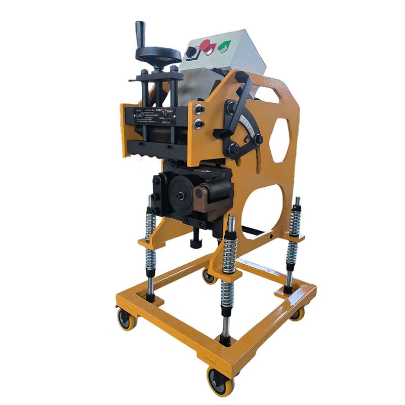
Define the Production Requirement
Before starting step groove machining, record the material, dimensions, incoming condition, required result, tolerance, batch or plate size, production volume, and downstream operation. Identify features that must not change and conditions that can affect safe loading, access, separation, or inspection.
The central planning focus is drawing interpretation, datum hierarchy, pass sequence, tool access, central lands, and inspection. Confirm which requirement governs the job and who may approve a change. Where applicable, consult ISO 9692-1 and AWS D1.1 information, while recognizing that project documents and local rules control the work.
Control the Main Variables
Effective step groove machining depends on interacting variables. The primary controls for this application are step dimensions, angle combination, plate thickness, pass order, tool reach. Changing several variables at once makes cause and effect difficult to understand, so establish a baseline and adjust one factor at a time.
| Variable | Why it matters | What to record |
|---|---|---|
| step dimensions | Influences geometry, contact, or process intensity | Target, actual condition, and approval for step dimensions |
| angle combination | Influences repeatability, handling, or inspection | Target, actual condition, and approval for angle combination |
| plate thickness | Influences geometry, contact, or process intensity | Target, actual condition, and approval for plate thickness |
| pass order | Influences repeatability, handling, or inspection | Target, actual condition, and approval for pass order |
| tool reach | Influences geometry, contact, or process intensity | Target, actual condition, and approval for tool reach |
For step groove machining, the control record should show the actual setup rather than only a nominal machine value. Include the relevant material condition, tooling or media identification, load or support arrangement, settings, measurement method, and operator.
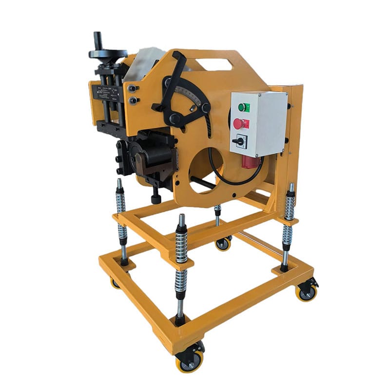
Build a Repeatable First-Piece Workflow
Use a documented first-piece workflow whenever step groove machining is introduced for a new part, plate, material, thickness, geometry, or finish requirement. A representative trial is more valuable than an unusually clean sample that avoids normal production difficulties.
- Verify the latest drawing, specification, material, units, and process orientation.
- Inspect the incoming condition and clean the approved datum or contact surfaces.
- Confirm machine capacity, guards, tooling or media, support, and utilities.
- Run a short, conservative step groove machining trial using documented settings.
- Stop safely, clean without altering the result, and inspect every controlling feature.
- Change one verified variable if correction is required, then repeat the trial.
- Record the accepted recipe and release production only after first-piece approval.
Reapprove step groove machining after a tool or media change, maintenance, impact, abnormal noise, loss of guide contact, material change, major load change, new compound, or revised acceptance requirement. These triggers prevent an old recipe from being used outside the conditions in which it was validated.
Evaluate Equipment and Consumables
Equipment for step groove machining should be evaluated against the complete working envelope: material, part or plate size, usable load, groove or finish requirement, tooling or media options, pass or cycle plan, handling, utilities, changeover, cleaning, inspection access, maintenance, and operator safety.
Review Yuanli’s beveling equipment range, then provide an actual application description instead of choosing from one headline specification. step groove machining capacity must be confirmed under the expected production conditions, not inferred from an isolated maximum value.
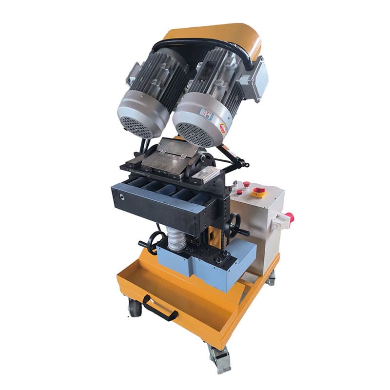
Inspect the Result
Inspection for step groove machining needs a defined method, suitable tools, agreed sampling locations, and a reaction plan. Measure the positions most likely to reveal variation, including starts, stops, recesses, long travel sections, shielded areas, or locations affected by support and handling.
Separate incoming variation from process variation. Record the condition before step groove machining, inspect the processed result, and verify any later assembly, cleaning, or handling step that can change the evidence. Use TWI butt-weld design guidance for relevant technical context without replacing the job specification.
Compare Process Choices
A useful process comparison considers quality, control, handling, and total production effort together. The table below prevents a decision based on one attractive feature while ignoring inspection or rework.
| Decision factor | Controlled approach | Uncontrolled shortcut |
|---|---|---|
| Requirement | Measured result tied to the drawing or finish specification | Visual judgment without an acceptance rule |
| Setup | Recorded tooling, media, load, datum, and settings | Settings copied from a different job |
| Trial | Representative first piece with approved inspection | Immediate full-batch production |
| Change | One variable adjusted against a defined symptom | Several settings changed together |
| Release | Actual readings and traceable approval | Pass/fail without evidence |
step groove machining should be selected on the basis of the complete production system. Labor, safe handling, separation, cleaning, inspection, maintenance, and rework can outweigh a small difference in nominal machining or cycle time.
Troubleshoot Common Problems
When the process becomes unstable, define the symptom before changing settings. Typical problems for this topic include lost datum, incorrect step depth, corner chatter, cumulative error. Record where the condition appears, its direction or pattern, when it began, and whether it follows a material, tool, media, load, operator, or maintenance change.
| Observed problem | Likely areas to check | Controlled response |
|---|---|---|
| lost datum | step dimensions, incoming condition, and inspection method | Stop, preserve evidence, verify the cause, and adjust one approved variable |
| incorrect step depth | angle combination, incoming condition, and inspection method | Stop, preserve evidence, verify the cause, and adjust one approved variable |
| corner chatter | plate thickness, incoming condition, and inspection method | Stop, preserve evidence, verify the cause, and adjust one approved variable |
| cumulative error | pass order, incoming condition, and inspection method | Stop, preserve evidence, verify the cause, and adjust one approved variable |
Preserve failed samples or measurement locations long enough to compare them with the corrected step groove machining result. Do not grind, polish, clean, or rework away the evidence before the responsible team understands whether the cause is input material, setup, equipment, consumables, handling, or inspection.
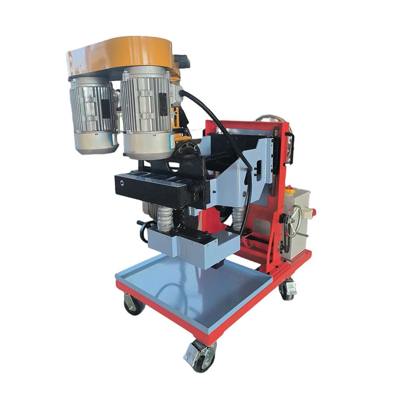
Plan Safety and Maintenance
step groove machining may involve rotating machinery, heavy workpieces, sharp edges, chips, dust, chemicals, noise, or stored energy. Follow the machine manual, guarding, lifting, PPE, housekeeping, and energy-isolation procedures. Operators must know which checks they may perform and which tasks require qualified maintenance personnel.
Consult OSHA machinery requirements as an authoritative safety reference while following local law and facility rules. A production improvement never justifies bypassing a guard, reaching into moving equipment, clearing a jam without isolation, or using an unapproved chemical.
Document Settings and Changes
A useful production record includes job and workpiece identification, material, dimensions, incoming condition, machine, tooling or media, compound or lubricant where applicable, settings, cycle or pass data, inspection results, operator, date, and corrective action.
Trend repeated exceptions by symptom and verified cause. Records can reveal whether variation follows step dimensions, angle combination, plate thickness, pass order, tool reach, a maintenance event, a supplier change, or an inspection method. Actual values provide more warning than a simple pass/fail mark.
Frequently Asked Questions
What is the first step in step groove machining?
Start step groove machining with the latest requirements and a representative incoming workpiece. Define the measurable result before selecting settings.
How should step groove machining be tested?
Use a controlled first-piece trial, keep other variables stable, inspect every required feature, and record the actual step groove machining result.
Why does step groove machining vary between batches?
Variation can follow incoming condition, step dimensions, angle combination, plate thickness, machine condition, handling, or inspection. Diagnose the pattern before changing the recipe.
When should step groove machining be reapproved?
Reapprove step groove machining after any change that can affect geometry, finish, cleanliness, handling, or safety, including maintenance and consumable replacement.
What information should a supplier receive?
Provide material, dimensions, drawings or finish criteria, tolerances, production volume, current process, known problems, and safe handling conditions for step groove machining.
Apply the Process to Production
A reliable step groove machining process begins with a clear requirement, representative trial, controlled variables, measurable inspection, and documented reaction plan. The method should solve the production problem while protecting the workpiece, operator, downstream process, and engineering intent.
For an application review, contact Yuanli with the material, dimensions, required result, tolerance, production volume, and current difficulty. These details allow step groove machining to be evaluated without inventing performance data, prices, certifications, or guarantees.