Table of Contents
Beveling cell layout starts with a clearly defined application. The useful starting point is the production decision: what must the equipment deliver, how will the result be checked, and which supporting operations are required? This guide uses YL-PKFZ95 as a relevant Yuanli product reference and separates published specifications from application conditions that require confirmation.
Beveling cell layout: the decision to resolve
A beveling cell must accommodate the entire plate movement, not just the machine footprint. Draw the incoming storage position, support frame, machine travel envelope, finished-plate route, and operator access. Check the arrangement with the longest and widest planned plate. Identify where lifting operations intersect with production and where temporary storage could obstruct access. Use the supplier's installation and operating instructions to establish equipment-specific clearances. A short travel path on a layout drawing may become awkward if the plate must be turned twice. Evaluate the cell through a complete job sequence before fixing floor locations or purchasing support equipment.
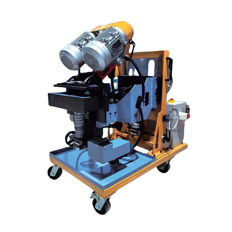
Beveling cell layout: map the complete material movement
In a beveling cell layout review, draw the path from incoming storage through loading, preparation, machining, inspection, and the next operation. Include temporary positions where plates wait between stages. Use the largest recurring workpiece to test the layout, and identify any turning or lifting that interrupts the sequence. The machine's reference footprint is only one part of the required working area.
For beveling cell layout, include largest planned plate in the layout review. Ask the equipment supplier to confirm model-specific access and support requirements. Check the plan with the people who will handle the actual plates, because a convenient-looking route can conceal awkward orientation changes. The resulting layout should explain where material goes and who controls each movement, rather than simply placing a machine symbol on a floor plan.
Beveling cell layout: measure elapsed time around the machine
In a beveling cell layout review, separate queue time, job preparation, workpiece handling, machine operation, inspection, and release. A stopwatch covering only cutting movement cannot describe the capacity of a work cell. Note which activities overlap and which depend on the same operator, lifting device, or inspection resource. Use accepted output as the end point of the measurement.
For beveling cell layout, the key question around incoming and outgoing routes is whether it limits the complete sequence. A faster machining stage may not increase output if a plate waits for support adjustment or final measurement. Begin with a few representative jobs and use the observations to identify practical improvements. Keep assumptions visible until they have been replaced by normal production records.
Beveling cell layout: prepare the next job without removing essential checks
In a beveling cell layout review, review which job-preparation tasks can be completed before the current batch finishes. Drawings, approved tools, gauges, material identification, and routing information can often be organised in advance. Tasks involving the machine itself must follow its operating and isolation instructions. The objective is to reduce avoidable waiting, not to eliminate required protections or inspections.
The beveling cell layout standard should define lifting interfaces clearly enough that another trained team can follow it. Measure changeover from the last accepted output of one job to the first accepted output of the next. This definition captures trial cuts and corrections that a narrower timing method would hide. Record recurring delays so the team can fix their causes rather than asking operators to compensate informally.
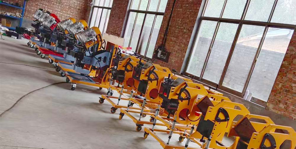
Walk one representative plate through the proposed cell
Use a floor plan and a clearly identified representative workpiece to follow the entire route on paper before moving equipment. Note its orientation at storage, loading, machining, inspection, and release. Include the plate and handling equipment envelopes, not only the machine outline. Identify any point where the part must reverse direction or wait in a shared aisle.
Review the plan with production and the personnel responsible for handling and installation. Confirm model-specific clearances from the supplier's instructions. If the longest recurring plate needs a different arrangement, show it as a defined route instead of assuming the normal layout can stretch to accommodate it. This makes the layout review a concrete production exercise with identifiable constraints.
Beveling cell layout: application comparison checklist
Use this beveling cell layout checklist to compare a proposal with the required production condition. The rows are discussion and verification points; they are not universal machine settings or guaranteed acceptance limits.
| Review item | Question to resolve | Useful evidence |
|---|---|---|
| Largest planned plate | Confirm largest planned plate for the actual workpiece and order. | Annotated drawing, sample identification, or order-specific scope |
| Travel envelope | Keep the requirement for travel envelope identical across the options. | Supplier response with stated conditions and exclusions |
| Incoming and outgoing routes | Observe incoming and outgoing routes during the complete proposed work sequence. | Representative trial record, including supporting work |
| Lifting interfaces | Record lifting interfaces with an identified sample or configuration. | Repeatable inspection record or signed configuration detail |
| Temporary storage | Assign responsibility for temporary storage before release. | Named owner and agreed deliverable in the handover record |
| Operator access | Revisit operator access when the approved conditions change. | Updated application review with a documented decision |
Beveling cell layout: relevant Yuanli equipment
For beveling cell layout, the YL-PKFZ95 product page provides a starting reference. Yuanli describes a reversible, self-propelled milling configuration for upper and lower bevel preparation, with floating height adjustment. Confirm the delivered configuration and the actual sample result before treating it as an approved production solution.
| Published item | Product-page reference |
|---|---|
| Motor power / power supply | 6,000 W / 380 V / 50 Hz |
| Plate thickness range | 4–95 mm |
| Bevel angle | 0°–75° (adjustable) |
| Groove types | K-, V-, X-, and Y-grooves; upper and lower bevels; 0° side milling |
| Bevel width | 20 mm per pass; up to 65 mm with multiple passes |
| Machine weight / dimensions | Approx. 450 kg / 1.0 × 1.0 × 1.5 m |
Published limits describe reference specifications; they do not establish that every maximum can be used simultaneously. Confirm the material, geometry, tooling, support, and delivered options for the intended job.
Beveling cell layout: prepare a technical enquiry
A useful beveling cell layout enquiry combines the workpiece drawing, material identification, incoming condition, expected order pattern, and the acceptance requirements. Add photographs that show the relevant geometry, with dimensions or an identified reference where needed. Include largest planned plate and operator access explicitly so the supplier can respond to the actual decision.
Compare the model above with the Yuanli beveling machine range. Ask which proposed conditions have already been demonstrated and which require samples. If the scope changes during discussion, update the enquiry and keep the revised requirements with the quotation.
For terminology used in joint cross-sections, see the TWI explanation of weld-joint preparation geometry; the applicable joint dimensions still come from the approved fabrication drawing and procedure. For related Yuanli guidance, review the existing groove-inspection guide.
Ready to discuss beveling cell layout for your production line? Contact Yuanli with the application package above and request a configuration review, sample-trial scope, and quotation. Use the enquiry form below to describe the job and the result you need.
Frequently asked questions
What should be defined first for beveling cell layout?
Start with largest planned plate and travel envelope. Connect them to the actual drawing, workpiece condition, and required result. The relevant model can then be evaluated against a specific application instead of a general product description.
Which evidence is useful when reviewing beveling cell layout?
Request an identified sample or configuration record covering incoming and outgoing routes and lifting interfaces. Preserve the method, observations, and any deviations. A selected photograph or a single nominal specification cannot replace the complete agreed verification.
Is YL-PKFZ95 automatically suitable for this application?
No. The YL-PKFZ95 page is a product reference for the beveling cell layout discussion. Suitability depends on the material, complete geometry, required output, supplied configuration, and the representative evidence accepted by the buyer and supplier.
Can beveling cell layout be approved from a catalogue alone?
A catalogue can support initial screening, but it does not establish every condition of the intended job. Resolve temporary storage and operator access before release. Use a representative trial whenever the required result or supporting method remains uncertain.
What should I send Yuanli about beveling cell layout?
Send the relevant drawing, material and incoming-condition details, expected quantities, and the acceptance criteria. Identify largest planned plate, incoming and outgoing routes, and any unresolved constraint. Request a written response with the recommended configuration and any conditions requiring a sample trial.