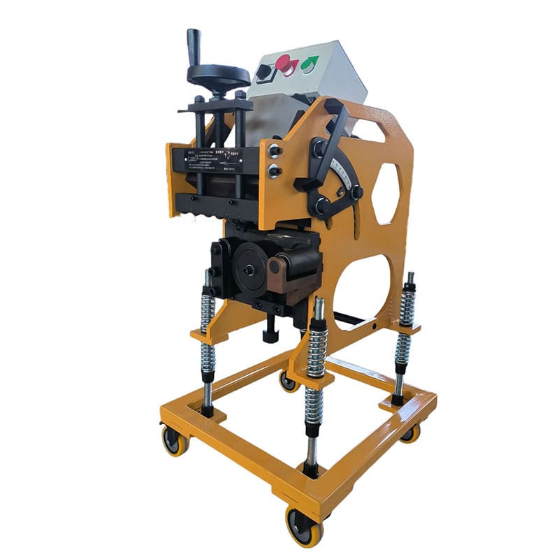
A weld can only be as consistent as the joint presented to the welder. When the groove is too narrow, the torch or electrode may not reach the root reliably. When it is unnecessarily wide, the joint consumes more filler metal, heat, and welding time. Choosing the right weld bevel angle is therefore a production decision, not a cosmetic detail.
There is no universal angle that works for every steel plate. Joint type, plate thickness, welding process, position, root opening, root face, backing arrangement, distortion control, and the qualified welding procedure all affect the final geometry. A value copied from another job may be unsuitable even when the base material appears similar.
This guide gives fabricators a practical method for selecting and verifying a weld bevel angle before production begins. It is written for welding engineers, production managers, quality teams, and buyers evaluating plate-beveling equipment. The goal is not to replace an approved drawing or welding procedure specification (WPS), but to help teams translate those requirements into a repeatable machined edge.
If you are building the wider preparation process, first review our guide to weld edge preparation. For equipment-selection criteria, see how to choose a steel plate beveling machine.
Table of Contents
What Does Weld Bevel Angle Mean?
The bevel angle is the angle formed between a prepared plate edge and a plane perpendicular to the plate surface. When two beveled plates form a V-groove, people may also discuss the included groove angle, which is the combined opening between both prepared faces. Confusing these two measurements can double an intended setting or produce a groove that does not match the drawing.
For example, two plates with equal 30-degree edge preparations form a nominal 60-degree included groove before fit-up effects are considered. The drawing should make clear whether it specifies the angle on one member or the total groove. Before setting a machine, the operator should confirm that the weld bevel angle is being measured from the correct reference surface.
Why the Angle Cannot Be Selected Alone
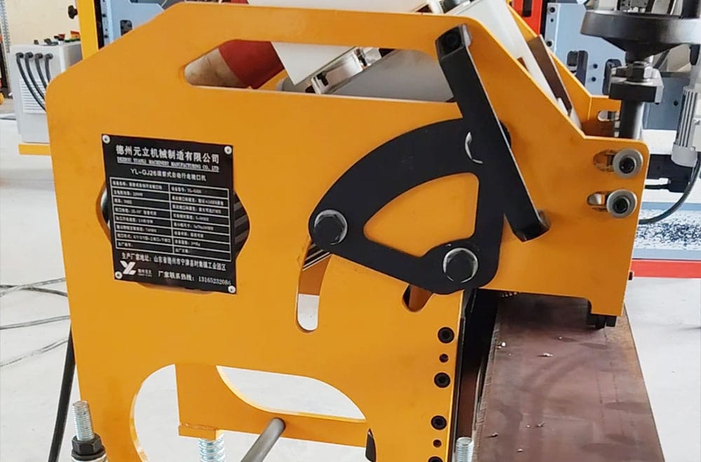
A weld bevel angle works together with the root face, root opening, groove depth, and alignment of the assembled plates. Changing the weld bevel angle or one of these supporting dimensions changes access to the root and the amount of weld metal required. A wider opening may improve access but also increases deposited volume. A larger root face may resist burn-through but make full penetration harder if the procedure is not adjusted.
Fit-up also changes what the welder sees. Tack welding can pull plates out of line, alter the root gap, or reduce the effective included angle. Measure the assembled joint, not only the loose plate. The best weld bevel angle is the one that remains within the approved joint tolerance after cutting, handling, tack welding, and restraint.
Start with the Drawing, Code, and WPS
The controlling documents for a weld bevel angle come before production preference. Review the joint detail, applicable code, contract requirements, WPS, and any procedure qualification record. ISO 9692-1 describes joint-preparation types for several welding processes on steel, while AWS D1.1 establishes requirements used in structural steel welding. The applicable document depends on the project.
Do not treat a familiar weld bevel angle as automatically prequalified. Material group, thickness range, welding process, position, backing, access side, and acceptance criteria may change the permitted joint. If the drawing and WPS appear inconsistent, stop and obtain an engineering decision rather than adjusting the machine on the shop floor.
Match the Joint Configuration to Welding Access
Joint configuration determines how the weld bevel angle is distributed and how the arc reaches the root. The following comparison is a planning guide, not a replacement for a qualified joint detail.
| Preparation | Typical reason to consider it | Key weld bevel angle check | Production concern |
|---|---|---|---|
| Square butt | Thin material or a procedure that does not require edge beveling | Confirm that no bevel is required and verify the root opening | Limited root access as thickness increases |
| Single V-groove | Access from one side or straightforward plate preparation | Verify each edge angle and the total included angle | Higher weld volume on thicker plate |
| Single bevel groove | Only one member can be prepared or joint geometry is asymmetric | Confirm the angle reference on the prepared member | Uneven shrinkage and access must be managed |
| Double V or X-groove | Both sides are accessible and weld volume or distortion needs control | Check upper and lower angles, land position, and alignment | Requires accurate two-sided preparation |
| J or U preparation | Reduced weld volume is important and machining is available | Angle alone is insufficient; radius and land are critical | More complex setup and inspection |
The TWI guidance on butt-weld design explains why access becomes more difficult as preparation angle or root gap is reduced. That trade-off is central: the groove must provide workable access without being wider than the qualified procedure requires.
Consider Plate Thickness and Root Geometry
Plate thickness affects the practical weld bevel angle, groove depth, heat input strategy, pass sequence, and the economic impact of extra groove volume. A small increase in weld bevel angle can add substantial cross-sectional area on thick plate. That means more filler, more arc time, and potentially more shrinkage. On thin plate, an overly aggressive preparation may remove too much support at the root.
Root Face, Root Gap, and Backing
Evaluate the weld bevel angle together with these three details. The root face controls the remaining uncut thickness. The root gap influences penetration and access after assembly. Backing can support the molten weld pool and may change the permitted preparation. Record all four values on the setup sheet so operators do not optimize one dimension while another moves out of tolerance.
Account for Welding Process and Position
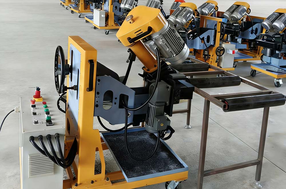
The selected weld bevel angle must also account for electrode size, torch geometry, transfer mode, travel technique, and shielding arrangement, which influence how much access the welder needs. A weld bevel angle that is practical for one process may restrict manipulation or gas coverage for another. Welding position matters as well because gravity changes puddle control and how the root and sidewalls are approached.
Use the qualified WPS to connect groove geometry with process variables. If the process changes, do not assume the same preparation remains acceptable. Run a controlled trial, inspect the result, and complete any required procedure review before releasing the revised weld bevel angle to production.
Compare Single-Sided and Double-Sided Preparation
When applying a weld bevel angle, single-sided preparation is often chosen when the reverse side is inaccessible or when handling constraints make two-sided work impractical. It simplifies plate positioning, but the groove volume and shrinkage may increase as thickness rises. The selected weld bevel angle must still give reliable root access throughout the joint.
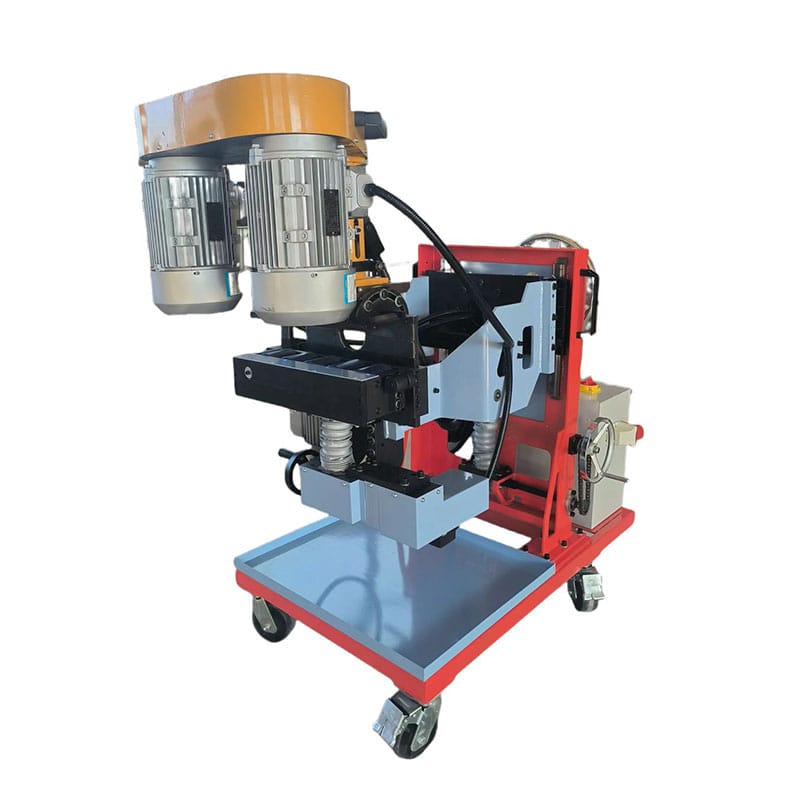
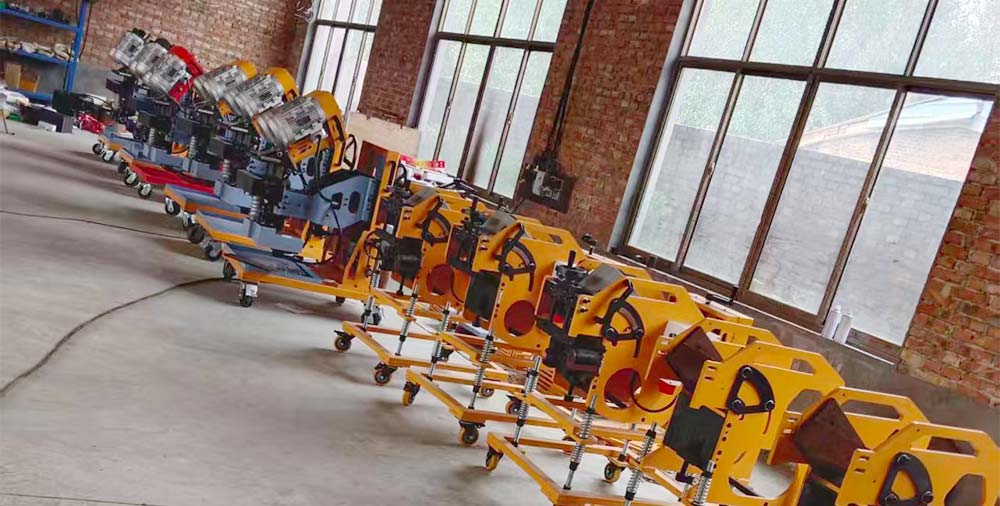
Double-sided preparation divides the groove between both faces. It can reduce the required deposited volume and help balance shrinkage, but only when the upper and lower preparations are aligned. For large plates that are difficult to turn, a machine that can process both faces without flipping the workpiece may simplify control. The YL-FZ900 beveling machine is designed for double-sided and step-groove preparation.
Connect the Required Angle to Machine Capability
Once engineering defines the weld bevel angle and tolerance, confirm that the machine can produce it across the required plate thickness, material, and bevel width. Check the adjustment range, cutter or milling-head configuration, clamping method, feed stability, edge access, and whether the machine references the plate surface consistently.
Weld bevel angle capacity should be judged on the complete groove, not a catalog angle alone. A machine may reach the nominal angle but not the required bevel width in one pass. Hard scale, an irregular flame-cut edge, or plate waviness can also affect the result. For wide machined preparations on heavy plate, review the operating range of equipment such as the YL-PK95 beveling machine. You can also compare the full beveling and polishing equipment range.
Use a First-Piece Setup and Inspection Routine
A repeatable weld bevel angle begins with a controlled first piece. Use material from the intended production condition whenever possible, including similar scale, flatness, hardness, and incoming edge quality.
- Confirm the drawing revision, WPS, material, thickness, joint type, and angle reference.
- Set the machine using a clean datum surface and the approved tooling configuration.
- Machine a short test section at conservative feed and cutting settings.
- Remove loose chips and measure angle, bevel width, root face, and surface condition.
- Assemble a representative fit-up and verify root opening and included groove angle.
- Record the accepted settings, tool identification, measurements, and inspector approval.
- Recheck after tool changes, significant plate-condition changes, or any impact to the setup.
Use a suitable bevel gauge or other calibrated method for the specified tolerance. Measure at several locations rather than only at the starting edge. A correct average can hide local variation that affects welding access.
Troubleshoot Bevel Geometry Before Welding
If the weld bevel angle changes along the plate, inspect the reference surface, guide or roller contact, clamping, plate flatness, tool wear, feed stability, and chip buildup. Do not compensate for an unstable setup by repeatedly changing the nominal angle. First remove the cause of variation.
A poor surface finish can indicate worn tooling, unsuitable cutting parameters, loose components, or intermittent contact. An inconsistent root face may come from plate waviness or an incorrect machine datum. Burrs and sharp edges should be handled according to the approved preparation process, without hand grinding away the controlled geometry.
When the assembled groove is too narrow despite correct loose-part measurements, review tack-welding sequence, restraint, angular distortion, and plate alignment. The weld bevel angle may be correct at the machine but ineffective after fit-up. Quality control should therefore include both individual-edge and assembled-joint checks.
Control Safety, Documentation, and Change
Producing a weld bevel angle and then welding the joint involves rotating tools, sharp edges, hot work, chips, noise, electrical equipment, and material-handling hazards. Follow the machine manual, site risk assessment, guarding requirements, lockout procedures, and required personal protective equipment. For welding operations in the United States, consult OSHA 1910 Subpart Q together with the requirements that apply to the facility and task.
Document the approved weld bevel angle as part of a controlled process. A setup sheet should identify the drawing and WPS revision, material and thickness range, machine, tooling, angle reference, target dimensions, tolerances, feed settings, inspection method, and reaction plan. This prevents informal adjustments from becoming undocumented process changes.
Frequently Asked Questions
What is the most common weld bevel angle?
Many shop examples use 30 degrees per plate edge to form a 60-degree included V-groove, but this is not a universal rule. The correct weld bevel angle must come from the applicable drawing, code, and qualified WPS.
Is bevel angle the same as groove angle?
Not always. A weld bevel angle normally describes one prepared edge relative to a perpendicular reference. Groove angle is the total included angle between the prepared faces. Confirm the terminology used on the drawing before setting the machine.
Does thicker plate always need a wider angle?
No. Thickness can influence the weld bevel angle, joint design, and weld volume, but a wider angle is not automatically better. Double-sided or compound preparations may reduce weld volume while preserving access. Use the qualified joint detail for the specific thickness range.
How should a weld bevel angle be measured?
Measure the weld bevel angle with the inspection method and tolerance specified by the quality plan, such as a suitable bevel gauge or calibrated measuring system. Check multiple positions, verify the root face, and inspect the assembled included angle where fit-up can change the geometry.
When should the first-piece setup be rechecked?
Recheck after tooling changes, machine adjustments, a new material or thickness, unusual plate condition, loss of datum contact, maintenance work, or measurements that trend toward the tolerance limit. Stable inspection prevents gradual drift.
Build a Repeatable Beveling Process
The right weld bevel angle is not selected from habit. It is derived from controlled documents, evaluated with the complete root geometry, matched to the welding process, translated into machine settings, and verified after fit-up. That sequence protects welding access without adding unnecessary groove volume.
If your team needs to produce single-sided, double-sided, or wide milled preparations on steel plate, share the material, thickness, required joint detail, production volume, and site constraints with our engineers. Contact Yuanli to discuss a suitable beveling process and machine configuration for your application.