A groove can have the correct bevel angle and still be difficult to weld when the remaining land is inconsistent. The weld root face controls how much uncut material remains at the root of a prepared joint. If it is too large, achieving the required penetration may become difficult. If it is too small, the root can lose support and become more sensitive to burn-through or fit-up variation.
A reliable weld root face is not selected in isolation. It works with the root opening, groove angle, plate thickness, welding process, position, backing arrangement, and the approved welding procedure specification. This guide explains how fabrication teams can translate a joint detail into a measurable and repeatable machined edge without inventing dimensions on the shop floor.
For the wider geometry behind groove preparation, review our weld bevel angle guide and the practical guide to weld edge preparation.
Table of Contents
What Is a Weld Root Face?
The weld root face, sometimes called the root land, is the portion of the plate edge that remains square after the bevel or groove has been machined. It is measured from the root edge to the point where the angled bevel begins. On a double-sided preparation, the remaining central land must also be positioned correctly between the upper and lower bevels.
Terminology varies between drawings, standards, and workshops. A drawing may use “root face,” “land,” or a symbol within the joint detail. Confirm the measurement reference and units before setting a machine. Do not assume that the bevel width automatically proves the weld root face is correct, because plate thickness and angle can change that relationship.
Why Root Face Geometry Matters
The weld root face helps balance two competing needs: adequate support at the root and sufficient energy or access for the welding process to achieve the specified result. A larger land can reduce the risk of the root edge melting away too quickly, but it also increases the section that must be penetrated. A smaller land reduces that barrier but demands tighter control of heat input, root opening, alignment, and travel technique.
Variation along a long plate creates a second problem. A welder may set parameters for the thickest part of the weld root face, while thinner sections respond differently. The result can be inconsistent penetration even though the nominal drawing dimension appears correct. Production control therefore needs a tolerance, a measurement method, and a reaction plan—not only a target value.
Read the Joint Detail Before Machining
Begin with the latest drawing, applicable code, WPS, procedure qualification records, and inspection plan. ISO 9692-1 describes joint-preparation types for several welding processes on steel, while AWS D1.1 is commonly referenced for structural steel welding. The governing document depends on the project and contract.
The approved detail should define the weld root face, root opening, bevel or groove angle, backing condition, and any asymmetry. If a dimension is missing or conflicts with the WPS, obtain an engineering decision. Increasing or reducing the land to make welding easier can be a procedure change, especially when it affects penetration, heat input, backing, or acceptance criteria.
Treat Root Face, Angle, and Gap as One System
A weld root face cannot be evaluated correctly without the other root dimensions. The table below shows how the variables interact during planning and inspection.
| Variable | Primary function | If excessive | If insufficient |
|---|---|---|---|
| Root face | Provides material support at the root | May restrict penetration | May increase burn-through sensitivity |
| Root opening | Provides access and space for the root pass | Increases fill volume and burn-through risk | Can restrict access and penetration |
| Bevel angle | Provides sidewall and tool access | Adds groove volume and heat demand | Can restrict electrode or torch access |
| Alignment | Keeps the roots in the intended position | High-low changes local root geometry | Poor fit-up makes the nominal dimensions misleading |
| Backing | Supports or shapes the root where approved | May change removal or inspection requirements | Unbacked roots may require tighter control |
Measure the assembled joint when possible. Tack welding, restraint, plate movement, and angular distortion can change the effective opening even when each loose plate has the correct weld root face. Inspection before and after fit-up reveals whether the machining process or the assembly process is creating the variation.
Match Root Geometry to the Welding Process
The welding process affects how much root access and support are practical. Electrode diameter, torch shape, transfer mode, current range, travel technique, and welding position all influence the acceptable combination. The weld root face used for one qualified process should not be copied to another simply because the material grade and thickness are similar.
Backing arrangements also matter. A permanent backing bar, removable backing, or open-root technique changes how the root is supported and inspected. Follow the qualified detail and confirm whether back gouging or reverse-side welding is required. The TWI guidance on butt-weld design provides useful context on access, root gaps, and preparation angles.
Account for Plate Thickness and Access
As plate thickness increases, a small change in bevel depth can change the remaining weld root face significantly. Thick plate also magnifies the cost of excess groove volume and makes handling more difficult. For single-sided grooves, verify that the selected geometry gives access through the full joint depth. For double-sided grooves, verify the central land and the alignment between both preparations.
Do not use one machine setting for a mixed stack of plate thicknesses unless the process has been validated for that range. Incoming thickness tolerance, scale, edge waviness, and flame-cut irregularity can shift the actual weld root face. Grouping similar plates and recording accepted settings reduces unnecessary adjustment.
Control the Weld Root Face During Beveling
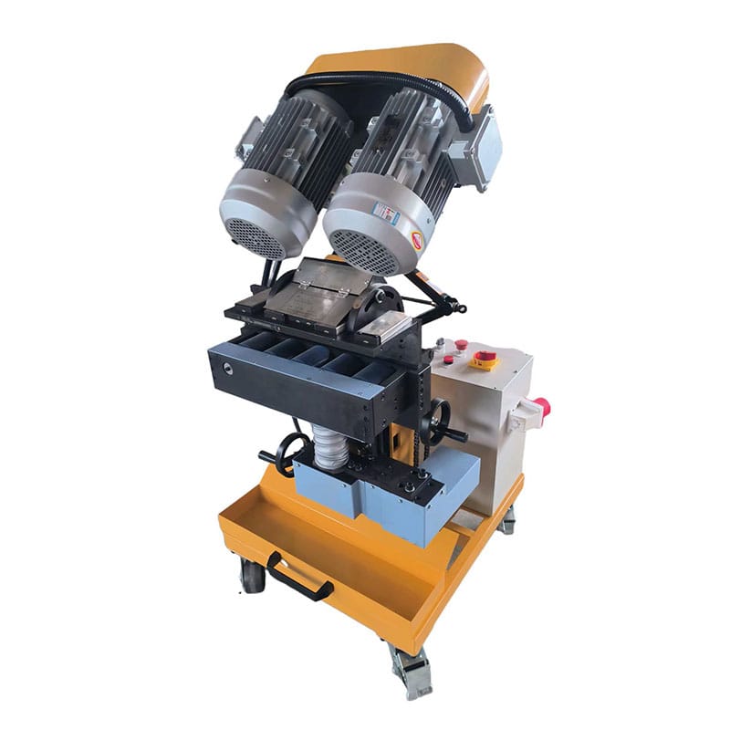
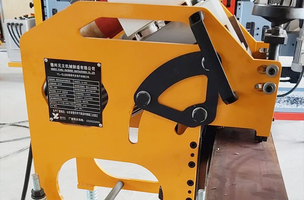
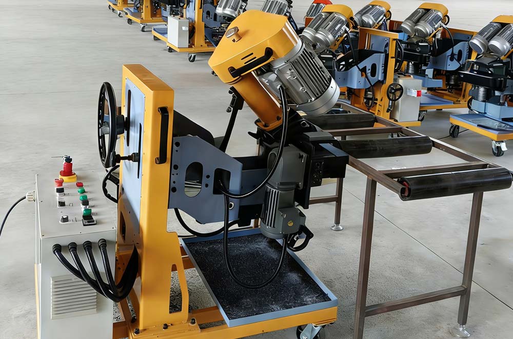
A plate beveling or milling machine controls the weld root face through cutter position, bevel depth, plate datum, clamping, guide contact, feed stability, and tool condition. Confirm that rollers or guides contact a clean and representative surface. Heavy scale, weld spatter, debris, or local plate curvature can lift the reference and alter the cut.
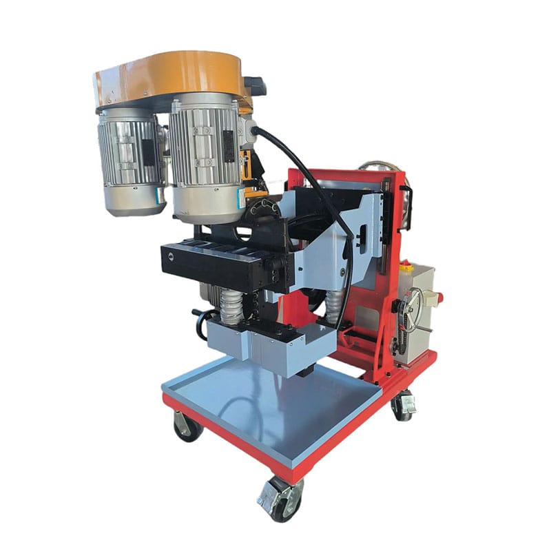
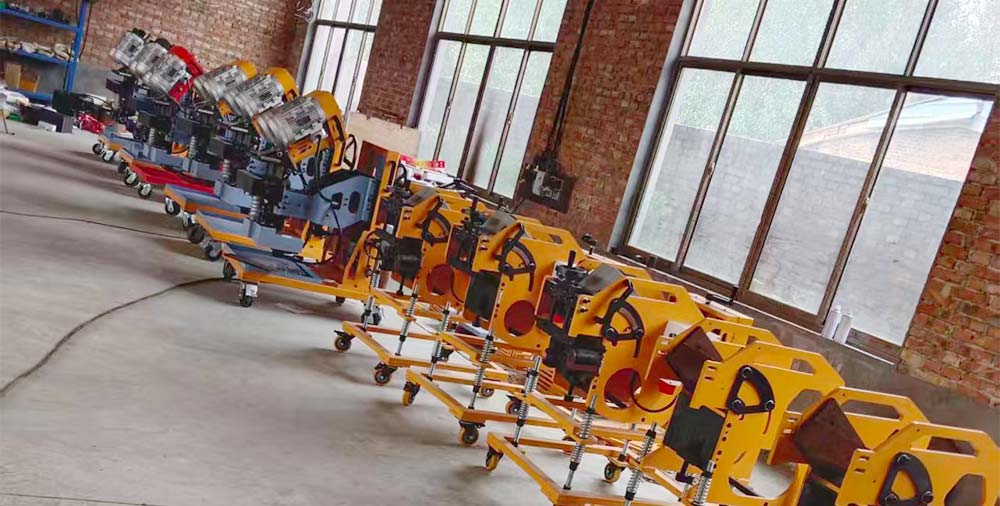
For wide milled preparations, check whether the required bevel can be produced in one stable pass or needs a planned sequence. The YL-PK95 beveling machine is intended for wide beveling work, while the YL-FZ900 supports double-sided and step-groove preparation. Machine selection should be based on the complete joint geometry, not the angle range alone.
Build a First-Piece Inspection Routine
Approve a first piece before releasing a batch. The first-piece routine should verify the drawing revision, material, thickness, angle reference, target weld root face, root opening, tooling, and inspection method. Use a representative section of the actual incoming edge condition rather than an unusually clean sample.
- Clean the datum and inspect the plate for scale, waviness, and edge damage.
- Confirm the machine angle, cutter position, guide contact, and feed direction.
- Machine a short test section using conservative parameters.
- Remove loose chips without grinding away controlled geometry.
- Measure bevel angle, bevel width, and weld root face at several locations.
- Assemble a representative fit-up and verify the root opening and alignment.
- Record the accepted settings, tool identification, measurements, and approval.
A suitable gauge or calibrated measuring method should match the drawing tolerance. Repeat measurements after a tooling change, impact, loss of guide contact, major material change, or maintenance. This prevents a drifting weld root face from reaching welding stations.
Common Root Face Problems and Corrections
When the weld root face is too large, first verify the angle reference, cutting depth, and plate datum. Do not immediately increase machine feed or force the tool deeper without checking capacity. When the land is too small, inspect for excessive bevel depth, worn guides, loose components, incorrect plate thickness settings, or a distorted incoming edge.
Tapering from one end to the other often points to plate curvature, unstable guide contact, incorrect clamping, or progressive tool movement. Local thin spots can come from scale breaking away beneath a guide or from damaged plate edges. Chatter and poor surface finish may indicate tool wear, excessive feed, loose components, or intermittent contact.
If the machined weld root face is correct but the assembled groove is not, investigate tack sequence, restraint, high-low, angular distortion, and handling. Separate the machining measurement from the fit-up measurement so the team corrects the true source of the problem.
Document Settings and Process Changes
A controlled setup sheet should identify the drawing and WPS revision, material and thickness range, machine, tooling, nominal weld root face, tolerance, bevel angle, root opening, feed settings, measurement method, inspection frequency, and reaction plan. Record actual results rather than only marking the operation complete.
Changes to tooling, machine configuration, welding process, backing, or acceptance requirements should trigger review. Safety controls must also remain part of the operation. Follow the machine manual, guarding and lockout procedures, and applicable requirements such as OSHA rules for welding, cutting, and brazing.
Frequently Asked Questions
Is weld root face the same as root gap?
No. The weld root face is solid material left at the root of the beveled edge. The root gap is the opening between assembled members. Both affect access and penetration, but they are measured differently.
What weld root face dimension should be used?
Use the dimension and tolerance specified by the approved drawing and WPS. There is no universal value for every material, thickness, process, position, and backing arrangement.
How should a weld root face be measured?
Use the inspection method required by the quality plan, such as an appropriate bevel gauge or calibrated measuring tool. Check several locations and confirm the reference surface.
Why check the joint after fit-up?
Fit-up can change the root opening, alignment, and effective access. Measuring the loose edge verifies machining; measuring the assembled joint verifies that the complete preparation still matches the approved detail.
When should the first piece be rechecked?
Recheck after tool replacement, machine adjustment, maintenance, a thickness or material change, loss of guide contact, unusual edge condition, or measurements approaching the tolerance limit.
Create a Repeatable Joint Preparation Process
A consistent weld root face comes from treating joint design, machining, fit-up, welding, and inspection as one process. Start with controlled documents, machine a representative first piece, measure the complete geometry, and record settings that operators can reproduce.
If your fabrication team needs to prepare single-sided, double-sided, or wide grooves on steel plate, review Yuanli’s beveling equipment range or contact us with the material, thickness, joint drawing, required tolerances, and production conditions. We can help evaluate a practical machine configuration without changing the engineering requirements of the joint.