A groove dimension has little production value unless the operator and inspector use the same datum, tool, location, units, and acceptance limits. plate beveling tolerance must therefore be translated from the drawing into a practical measurement routine before full-length machining begins.
This guide explains how fabrication teams can control plate beveling tolerance for bevel angle, bevel width, groove depth, root face, straightness, and double-sided alignment. It also shows how to separate machine drift from incoming plate variation and later fit-up problems.
For related geometry, review our weld bevel angle guide and weld root face guide. These dimensions work together, but one measurement does not automatically prove that every other feature is acceptable.
Table of Contents
What Plate Beveling Tolerance Means
plate beveling tolerance is the permitted variation around a specified groove dimension. The requirement may apply to angle, width, depth, land, offset, straightness, surface condition, or a relationship between upper and lower preparations. The drawing or quality plan should identify which features control acceptance.
A nominal value alone is not a complete plate beveling tolerance. Production needs an upper and lower limit or another defined acceptance rule, the reference surface, units, measurement method, sampling frequency, and action to take when a result approaches or exceeds the limit.
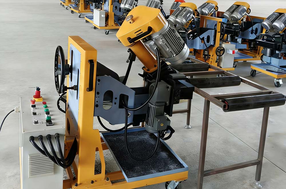
Start with Controlled Documents
Before evaluating plate beveling tolerance, confirm the latest drawing, welding procedure specification, material grade, actual thickness, inspection plan, and any applicable code. Resolve missing or conflicting dimensions through the responsible engineering or quality authority rather than choosing a convenient shop value.
ISO 9692-1 describes several steel joint-preparation types, while AWS D1.1 is widely referenced for structural steel welding. The contract and approved procedure determine the actual plate beveling tolerance; a general standard reference does not override project documents.
Define Datums and Measurement References
Every plate beveling tolerance check begins at a datum. A gauge placed on scale, a warped surface, a damaged edge, or a different plate face can produce a different reading even when the groove has not changed. Mark the orientation and clean the reference without grinding away controlled material.
Measure actual plate thickness when it affects plate beveling tolerance. Bevel angle, width, depth, and root face are geometrically related, so thickness variation can change visible bevel width even when the cutter angle remains stable. Avoid using one derived dimension as proof of another unless the drawing permits it.
Inspect Every Controlling Groove Feature
A complete plate beveling tolerance inspection checks all dimensions that control welding and assembly. Angle affects torch or electrode access and groove volume. Root face affects the remaining material at the root. Groove depth or width shows how far machining progressed. Straightness and taper reveal changes along the plate.
| Feature | Why it matters | Suggested inspection evidence |
|---|---|---|
| Bevel angle | Controls groove access and cross-section | Angle reading at defined stations |
| Root face | Controls remaining land at the root | Direct measurement at start, middle, and end |
| Bevel width or depth | Confirms cutter position and material removal | Calibrated dimensional reading |
| Straightness and taper | Detect guide, support, or plate changes | Multiple readings plotted by location |
| Upper/lower alignment | Controls double-sided central land | Independent face measurements and section check |
| Surface condition | Identifies chatter, tears, or local damage | Visual record against approved criteria |
Do not accept plate beveling tolerance from a single convenient location. Long plates can show taper, curvature, guide contamination, support changes, or progressive tool wear. Include the positions most likely to reveal variation.
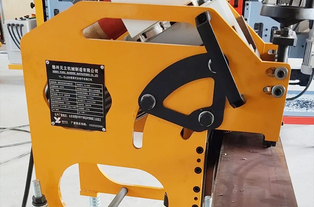
Choose Suitable Inspection Tools
Select tools that suit the plate beveling tolerance range, resolution, contact geometry, and working environment. A bevel gauge, protractor, caliper, depth gauge, straightedge, template, or dedicated fixture may be appropriate depending on the drawing. Calibrated tools should be within their required status and protected from damage.
Measurement capability must be adequate for the plate beveling tolerance. If two trained inspectors obtain materially different values, review gauge seating, burr removal, lighting, reference surfaces, tool resolution, and the written method. NIST provides authoritative calibration resources for understanding measurement traceability.
Build a First-Piece Inspection Routine
Approve a first piece before releasing a batch to the plate beveling tolerance plan. The first piece should represent the normal incoming edge, material thickness, plate support, tooling, and planned production direction rather than an unusually easy sample.
- Verify drawing, WPS, material, thickness, units, and groove orientation.
- Inspect and clean the datum and incoming edge.
- Confirm tooling, cutter position, guide contact, clamping, and plate support.
- Machine a short section with conservative approved parameters.
- Remove loose chips without altering the groove.
- Measure every controlling feature at several locations.
- Record the accepted settings, results, tool identification, and approval.
Repeat first-piece approval when a change can affect plate beveling tolerance, including tool replacement, machine adjustment, maintenance, material or thickness change, loss of guide contact, impact, abnormal vibration, or a new drawing revision.
Plan Production Sampling
A production sampling plan for plate beveling tolerance should consider plate length, batch size, process stability, tool life, and the consequence of a missed defect. Start, middle, and end readings are often useful for finding taper, but the approved quality plan must define the required frequency.
Use additional trigger checks when plate beveling tolerance may have changed. Examples include a damaged insert, sudden sound change, plate movement, interrupted cut, unusual scale, maintenance work, or a reading moving toward the reaction limit. Sampling should detect drift before an entire batch requires disposition.
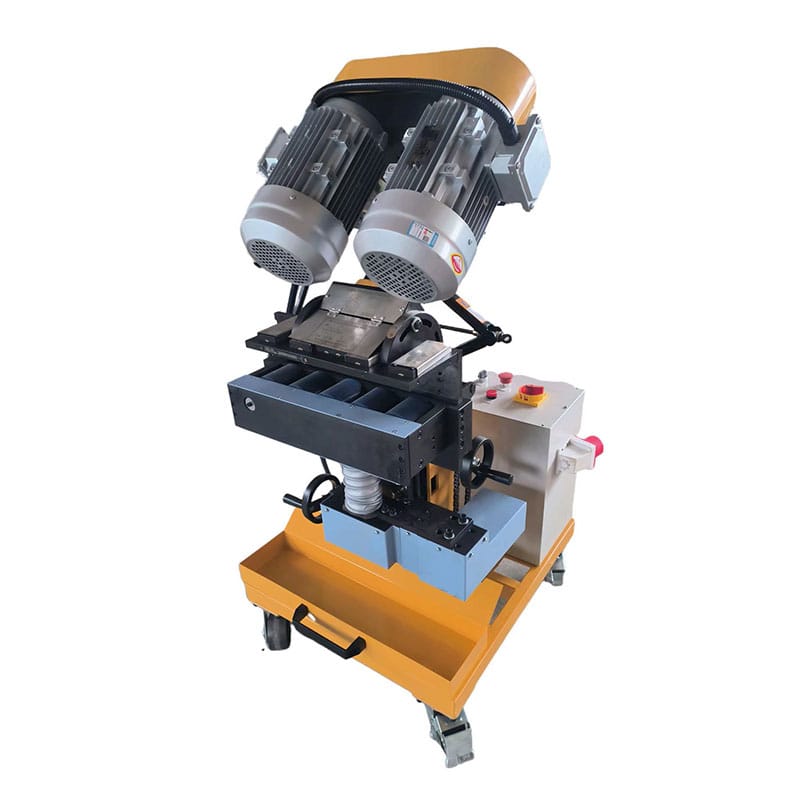
Diagnose Common Measurement Problems
When plate beveling tolerance readings disagree, describe the symptom precisely. A tapered root face points toward different causes than a correct land with an incorrect angle. Preserve the measurement locations and avoid immediate grinding that removes evidence.
| Observed problem | Areas to investigate | Controlled response |
|---|---|---|
| Angle readings vary by inspector | Gauge seating, scale, burrs, method, resolution | Clean the datum and repeat the defined method |
| Root face tapers along travel | Guide contact, plate curvature, support, looseness, wear | Measure start-middle-end and inspect the machine datum |
| Width passes but angle fails | Thickness variation or an incorrect geometric assumption | Measure controlling features independently |
| Local thin land | Damaged incoming edge, debris under guide, interrupted contact | Isolate the location and verify the actual cause |
| Double-sided land is off center | Unequal depths, wrong thickness reference, face misalignment | Check both setups and central-land position |
Correct the verified cause of the plate beveling tolerance problem rather than compensating with undocumented settings. If material has already moved outside the acceptance limit, follow the nonconformance and engineering-disposition process.
Connect Machining Inspection to Fit-Up
A plate can pass plate beveling tolerance inspection while loose and still produce an unacceptable assembled joint. Tack sequence, root opening, high-low, angular distortion, and restraint can change the effective groove. Add a fit-up check when the drawing or quality plan requires it.
Separate machining evidence from assembly evidence. Our guide to plate edge milling for weld preparation explains why stable cutting and later handling must be managed together. The beveling machine controls the edge, not every downstream variable.
Record Results and Reaction Limits
A useful plate beveling tolerance record includes job and plate identification, drawing revision, material, actual thickness, machine, tooling, settings, measurement tool, locations, actual readings, operator, inspector, date, and corrective action. Record numbers rather than only pass or fail when the plan permits it.
Trend plate beveling tolerance results over the tool-life and maintenance cycle. A gradual shift can be corrected before the limit is exceeded. Establish a reaction limit inside the final tolerance when justified by process capability and approved by the quality system.
Frequently Asked Questions
Is bevel width enough to verify the angle?
No. Plate thickness and groove depth affect width, so plate beveling tolerance should be checked using the controlling measurement specified by the drawing.
How many locations should be measured?
Follow the approved sampling plan. Use enough locations to detect taper and local variation in plate beveling tolerance, including start, middle, end, and trigger areas where appropriate.
What should happen when a reading is near the limit?
Apply the reaction plan, repeat the plate beveling tolerance check with the verified method, and review process drift before continuing the batch.
Should the groove be checked after fit-up?
Yes when required. Assembly can change root opening and alignment even when loose-plate plate beveling tolerance is correct.
Can measurements be taken while the cutter is moving?
No. Stop the machine and stabilize the workpiece according to the manual and site procedure. OSHA’s machine-guarding requirements provide a relevant safety reference.
Make Groove Quality Repeatable
Repeatable plate beveling tolerance comes from controlled documents, clear datums, suitable tools, first-piece approval, planned sampling, and a defined response to drift. Measure every feature that governs the joint instead of relying on one convenient proxy.
If you need equipment for a defined groove and inspection requirement, review Yuanli’s beveling equipment range or contact Yuanli with the material, thickness, joint drawing, required plate beveling tolerance, plate dimensions, and production conditions.