Table of Contents
Bevel angle reference starts with a clearly defined application. A practical review connects the actual workpiece with an agreed acceptance method. Catalogue figures become useful only after that connection is clear. This guide uses YL-PKFZ95 as a relevant Yuanli product reference and separates published specifications from application conditions that require confirmation.
Bevel angle reference: the decision to resolve
A thirty-degree callout can represent different geometry depending on whether the drawing refers to one edge, an included groove, or the plate surface. The operator's scale may use another convention. Resolve those references before setting the machine. On a paired joint, show both mating parts and identify whether the groove is symmetrical. A clear annotated sketch is usually more useful than a verbal angle instruction. Include the root face and fit-up condition so the inspection team evaluates the same intended result. The equipment supplier can confirm how its adjustment scale relates to the required edge, but the approved joint design remains the fabrication team's responsibility.
Bevel angle reference: separate the nominal plate from the actual workpiece
In a bevel angle reference review, the material description and nominal thickness define only part of the starting condition. Check the actual plate where it will be supported, guided, and machined. Local thickness variation, an uneven edge, or a different incoming cutting route may change the stock that must be removed. Record these observations before adjusting the machine.
A bevel angle reference investigation should connect included joint angle to the measured starting condition. Use identified locations so the team can compare the same points before and after machining. Avoid interpreting every finished-edge variation as an angle-setting error. Where the incoming condition exceeds the agreed application envelope, resolve it with the responsible supplier or production team. The machine selection and inspection plan should both reflect the material that will really reach the work cell.
Bevel angle reference: choose inspection points that reveal the problem
In a bevel angle reference review, inspection coverage should follow the physical risk of the feature. Include the beginning, middle, and end of a long edge where appropriate, together with corners or other transitions that may behave differently. Identify the measuring instrument, datum, and orientation so repeated readings are comparable. The required tolerances come from the approved drawing or fabrication specification.
For bevel angle reference, add a specific check for mating part orientation. Retain individual readings rather than only an average, because a local defect can disappear inside a satisfactory mean. If measurements disagree, first establish whether the inspection method is repeatable. A dispute about the gauge or reference cannot be solved by changing the machining setup blindly. Use the accepted sample and measurement record together when explaining the result to production.
Bevel angle reference: connect the prepared edge to fit-up
In a bevel angle reference review, the prepared edge is an intermediate feature in a larger fabrication sequence. Confirm how it will meet its mating component and which dimensions become important during assembly. A groove can meet an isolated edge drawing but still be incorrectly oriented or paired with the wrong opposite-side preparation. Preserve part identification through turning, transport, and storage.
A bevel angle reference review therefore needs root geometry as well as a machining check. Where the downstream operation has an approved procedure, use its requirements to define the preparation rather than inventing a universal joint recommendation. Include the relevant fit-up verification in the trial or handover. Keeping that connection visible helps the team evaluate equipment on the complete fabrication outcome instead of the appearance of one machined surface.
Use a paired-edge sketch to resolve the convention
Draw both mating plates in their assembly orientation. Mark each individual bevel and show the included opening between them. For a symmetric idealised V preparation, two equal 30-degree edge angles measured from the square-edge reference form a 60-degree included opening. This illustrates terminology and does not prescribe a weld design.
Now identify the reference used by the machine adjustment scale. Ask the supplier to explain how the required individual edge is set and measured on that configuration. Add the root face and any specified gap to the sketch without combining them into the angle callout. Keep the annotated sketch with the job so a later shift or subcontractor does not recreate the interpretation from an isolated number.
Bevel angle reference: application comparison checklist
Use this bevel angle reference checklist to compare a proposal with the required production condition. The rows are discussion and verification points; they are not universal machine settings or guaranteed acceptance limits.
| Review item | Question to resolve | Useful evidence |
|---|---|---|
| Individual bevel angle | Confirm individual bevel angle for the actual workpiece and order. | Annotated drawing, sample identification, or order-specific scope |
| Included joint angle | Keep the requirement for included joint angle identical across the options. | Supplier response with stated conditions and exclusions |
| Machine scale convention | Observe machine scale convention during the complete proposed work sequence. | Representative trial record, including supporting work |
| Mating part orientation | Record mating part orientation with an identified sample or configuration. | Repeatable inspection record or signed configuration detail |
| Root geometry | Assign responsibility for root geometry before release. | Named owner and agreed deliverable in the handover record |
| Approved sketch | Revisit approved sketch when the approved conditions change. | Updated application review with a documented decision |
Bevel angle reference: relevant Yuanli equipment
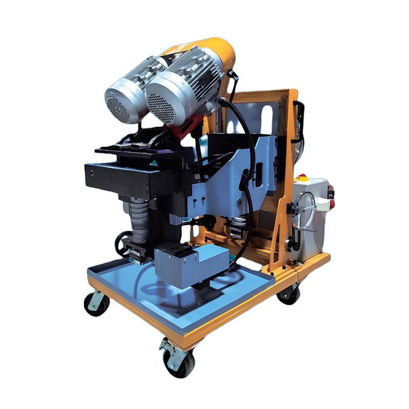
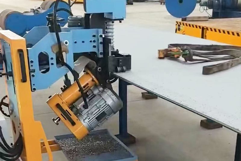
For bevel angle reference, the YL-PKFZ95 product page provides a starting reference. Yuanli describes a reversible, self-propelled milling configuration for upper and lower bevel preparation, with floating height adjustment. Confirm the delivered configuration and the actual sample result before treating it as an approved production solution.
| Published item | Product-page reference |
|---|---|
| Motor power / power supply | 6,000 W / 380 V / 50 Hz |
| Plate thickness range | 4–95 mm |
| Bevel angle | 0°–75° (adjustable) |
| Groove types | K-, V-, X-, and Y-grooves; upper and lower bevels; 0° side milling |
| Bevel width | 20 mm per pass; up to 65 mm with multiple passes |
| Machine weight / dimensions | Approx. 450 kg / 1.0 × 1.0 × 1.5 m |
Published limits describe reference specifications; they do not establish that every maximum can be used simultaneously. Confirm the material, geometry, tooling, support, and delivered options for the intended job.
Bevel angle reference: prepare a technical enquiry
A useful bevel angle reference enquiry combines the workpiece drawing, material identification, incoming condition, expected order pattern, and the acceptance requirements. Add photographs that show the relevant geometry, with dimensions or an identified reference where needed. Include individual bevel angle and approved sketch explicitly so the supplier can respond to the actual decision.
Compare the model above with the Yuanli beveling machine range. Ask which proposed conditions have already been demonstrated and which require samples. If the scope changes during discussion, update the enquiry and keep the revised requirements with the quotation.
For terminology used in joint cross-sections, see the TWI explanation of weld-joint preparation geometry; the applicable joint dimensions still come from the approved fabrication drawing and procedure. For related Yuanli guidance, review the existing groove-inspection guide.
Ready to discuss bevel angle reference for your production line? Contact Yuanli with the application package above and request a configuration review, sample-trial scope, and quotation. Use the enquiry form below to describe the job and the result you need.
Frequently asked questions
What should be defined first for bevel angle reference?
Start with individual bevel angle and included joint angle. Connect them to the actual drawing, workpiece condition, and required result. The relevant model can then be evaluated against a specific application instead of a general product description.
Which evidence is useful when reviewing bevel angle reference?
Request an identified sample or configuration record covering machine scale convention and mating part orientation. Preserve the method, observations, and any deviations. A selected photograph or a single nominal specification cannot replace the complete agreed verification.
Is YL-PKFZ95 automatically suitable for this application?
No. The YL-PKFZ95 page is a product reference for the bevel angle reference discussion. Suitability depends on the material, complete geometry, required output, supplied configuration, and the representative evidence accepted by the buyer and supplier.
Can bevel angle reference be approved from a catalogue alone?
A catalogue can support initial screening, but it does not establish every condition of the intended job. Resolve root geometry and approved sketch before release. Use a representative trial whenever the required result or supporting method remains uncertain.
What should I send Yuanli about bevel angle reference?
Send the relevant drawing, material and incoming-condition details, expected quantities, and the acceptance criteria. Identify individual bevel angle, machine scale convention, and any unresolved constraint. Request a written response with the recommended configuration and any conditions requiring a sample trial.